
Being able to simulate highly complex and fully featured CAD-assemblies in minutes including every connection, be it weld, bolt or glued in minutes makes Simsolid the most advanced FEA solution on the market.
It liberates the user from geometry simplification and meshing: the two most time-consuming, expertise extensive and error-prone tasks done in traditional structural analysis. Coupled with its intuitive user interface, real world scenarios can be simulated in the earliest stages of development. The native compatibility with common CAD file type enables a seamless integration in the development workflow.
Simsolid supports all typical connection types (nut & bolt, gluing, welding, rivetting and sliding connection) with linear static, modal and thermal analysis. Coupled analysis make it possible to combine non-linear and transient effects.
SimSolid delivers the speed and accuracy to reduce development times and time to market times, beating the competition.
Why Simsolid?
Eliminates geometry simplification
The unique technology of Simsolid completely eliminates geometry simplification and meshing: the two most time-consuming, expertise extensive and error-prone tasks done in traditional structural analysis.
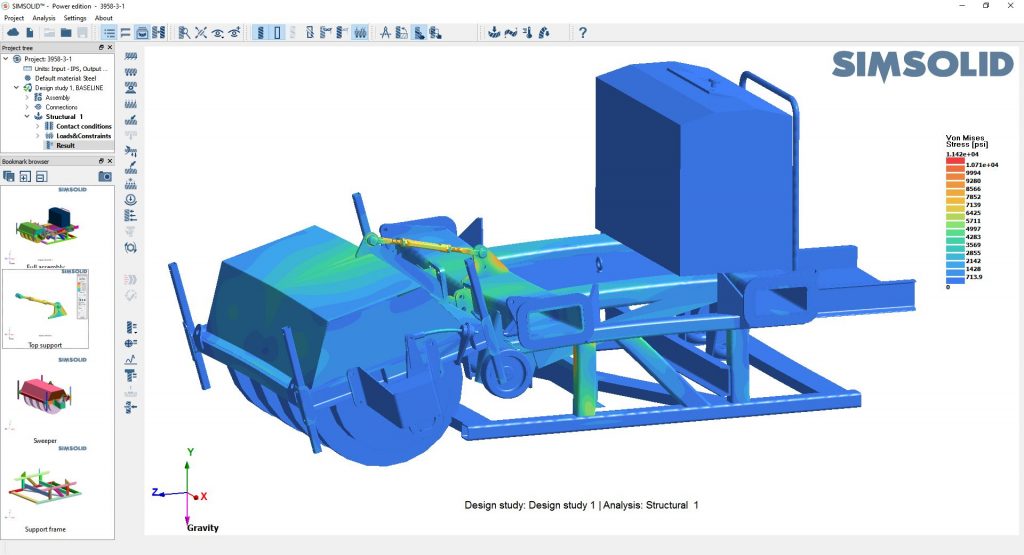
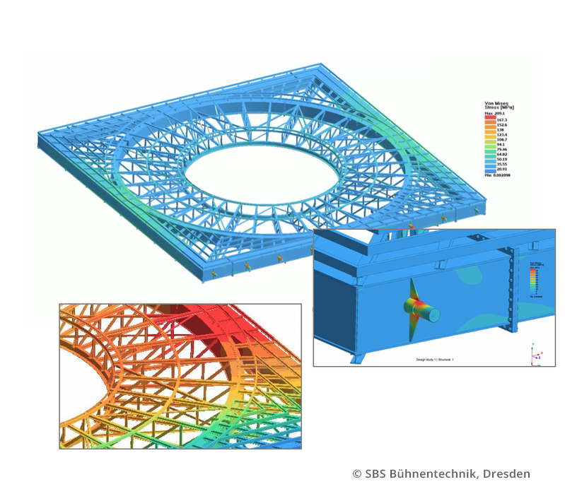
Analyze complex assemblies
Simsolid has been developed to make it possible to analyze big and complex assemblies which can not be analyzed with a conventional FEA. SimSolid is highly gap-tolerant and able to also work with irregular and intersecting surface geometries.
Results in seconds to minutes
Simsolid is fast. On a desktop class pc solutions will be calculated in seconds to minutes which makes it possible to analyze and evaluate multiple design iterations in no time.
Core functions
Solver options
- Linear static, modal, thermal, coupled thermal analysis
- Material- and geometric non linear analysis, transient dynamics (time, frequency and random response)
- life cycle and endurance analysis
Supported connectors
- Welded and glued connections
- Virtual connectors
- Welds (point weld, laser-weld, fillet weld), riveting
Boundary conditions
- Bearings
- Displacements
- Force, pressure, gravity, thermal loads, innertia
- Inertia relief, hydrostatic loads
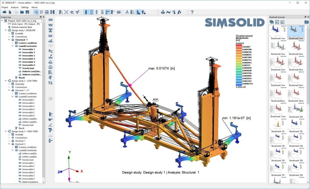
Result types
- Contour and rainbow diagrams for part forces and stresses
- Animation of part deformation
- Max-/minimum-label, selected points, XY-diagrams, reaction and contact forces
- Forces on nuts and bolts, point weld forces
- Frequency and factor of safety
Additional functions
- Rigid body interaction
- Tightening of nuts and bolts
- Modal analysis
CAD- compatibility
- Natively compatible to all major CAD file types. including:
- CATIA, NX, PTC/Creo, Inventor, Fusion 360, SOLIDWORKS, SolidEdge, Onshape, JT, STEP, VDA, Parasolid, ACIS, PLMXML, CGR, ST

